Pierre Kostantine
Electrical Engineering Student at Toronto Metropolitan University
I am a motivated third year Electrical Engineering student at Toronto Metropolitan University with a strong interest in practical, real world design. I work well both independently and within team environments, especially when solving technical problems and troubleshooting systems. I enjoy applying theoretical concepts through labs and projects, and I am particularly interested in turning those concepts into clear, functional engineering designs.

My Projects
A selection of my personal projects.
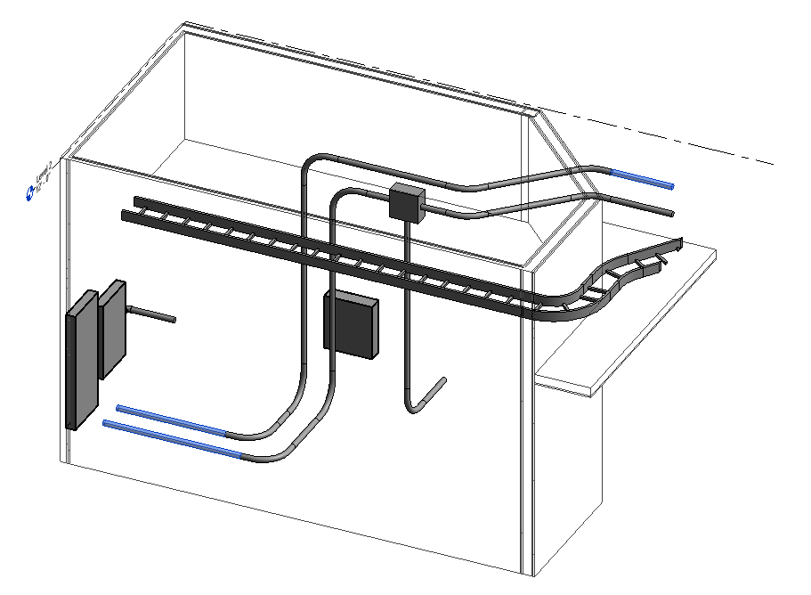
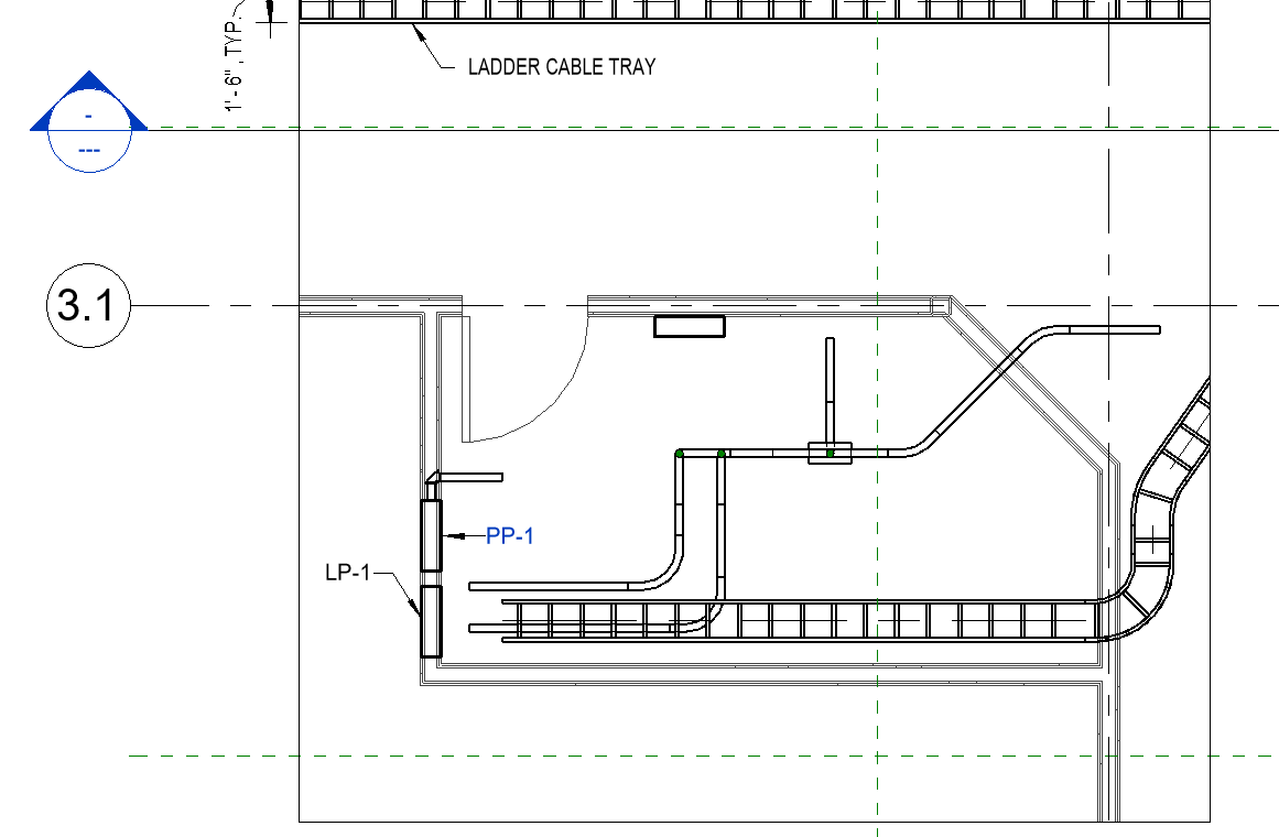
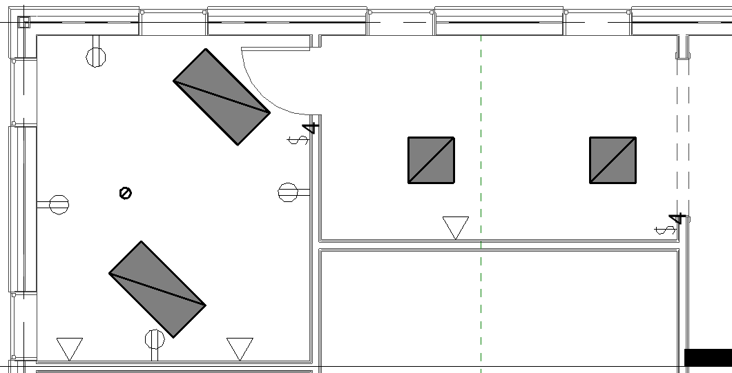
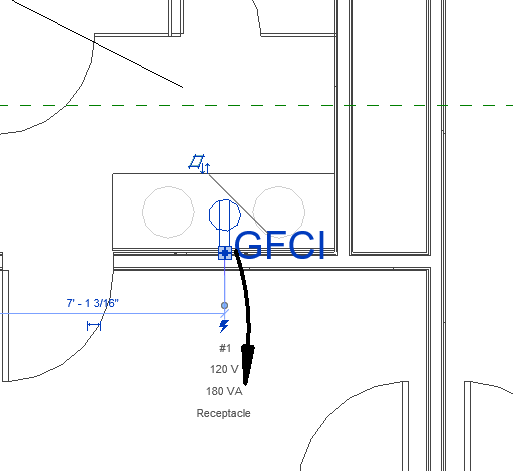
Revit Electrical Design for First Floor of Building
I developed a complete first floor electrical design using Autodesk Revit 2026, creating coordinated power and lighting layouts based on an architectural model. The project involved placing and modifying lighting fixtures, receptacles, electrical panels, circuits, conduits, and cable trays while maintaining proper coordination with linked Revit and AutoCAD files. Electrical systems were organized through accurate circuit assignments and panel connections to reflect realistic power distribution.
In addition to the layout, I generated detailed lighting and electrical schedules directly from the model, including lighting panel schedules, power panel schedules, and a lighting fixture schedule. These schedules were organized into a dedicated schedules sheet, alongside a separate first floor power sheet that clearly presents the electrical layout. This project demonstrates my ability to use Revit 2026 for electrical modeling, coordination, scheduling, and professional drawing production, while applying industry relevant workflows suitable for real world electrical design and certification preparation.
Revit 2026
Electrical Design


FPGA Implementation of an 8-Bit Processor
I developed a complete processor in VHDL and built it on the Altera Cyclone II DE2 FPGA, showing a complete digital system implementation from architecture to hardware. The processor has storage components, a microcode-controlled control unit, and an 8-bit Arithmetic Logic Unit supporting arithmetic, Booleans, bitwise manipulations, comparisons, as well as user-defined operations. The processor further includes a Mealy finite state machine and a 4-to-16 decoder, handling operation selection, as well as input storage via gated D latches. I used Quartus II waveform simulations, and real-time verification on the FPGA, with the resulting outputs displayed on a seven-segment display through a decoder. This project shows my ability to design and implement a functional digital system while also demonstrating how such a processor can be applied to everyday applications, such as basic computing or calculator style operations. At the same time, it serves as a strong foundation for further exploration and more advanced development in FPGA based processor and digital system design.
VHDL
FPGA
Computer Architecture
Digital Logic


Design of a 4 Stage MOSFET Amplifier
I designed and analyzed a four stage MOSFET voltage amplifier to meet specific performance requirements, including gain, bandwidth, power consumption, and output swing. The amplifier uses three cascaded common source stages to achieve high voltage gain, followed by a common drain output stage to buffer the load and reduce output sensitivity. The project included full device level design, with biasing networks, transistor sizing, and verification that every device remained in saturation. I performed hand calculations for operating points, transconductance, gain, and bandwidth, then validated the design with SPICE simulation in KiCad. The final design achieved more than 60 dB of voltage gain, over 30 MHz of bandwidth, greater than 1.5 V peak to peak output swing, and under 1 mW of power consumption, while revealing practical effects such as interstage loading and non ideal large signal behavior.
Analog Design
MOSFET
SPICE
KiCad


Design of an Autonomous Line-Following Car
I designed and built a line following autonomos car model using Hardware C Language on an Arduino Mini, demonstrating a complete embedded systems project from control logic to physical hardware behavior. The system uses two analog sensors to detect a black line on a contrasting surface and dynamically control two DC motors to maintain accurate path tracking through forward motion and tank turn corrections. Threshold based decision logic determines directional adjustments, while additional control features handle real world track conditions, including ignoring the start marker, stopping at intersections, and a 180 degree turn after completing one full lap. This project shows my ability to translate sensor data into real time motor control, integrate software with hardware components, and design reliable autonomous behavior, while also serving as a strong foundation for more advanced robotics and embedded systems development.
C
Arduino
Embedded Systems
Robotics
Contact Me
Email: [email protected]
Phone: (647) 504-3982
My Certifications and Achievements


